
 EN
EN

A redundant switch configuration is one of the most effective strategies a network team can deploy to prevent costly downtime. When a primary switching device fails unexpectedly, a redundant switch steps in automatically, maintaining active data paths and keeping critical business services online without manual intervention. Understanding exactly how this process works helps network architects make smarter infrastructure decisions.
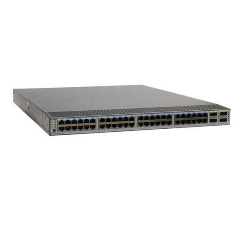
Every data center and enterprise network carries the risk of hardware failure. A single redundant switch deployment can mean the difference between a seamless user experience and hours of disruptive outage. This article explores the core mechanisms behind redundant switch configurations, how they respond to hardware failures, and what design principles ensure they perform reliably when it matters most.
Core Mechanisms Inside a Redundant Switch Setup
Failover Protocols That Drive Redundancy
The foundation of any redundant switch configuration lies in its failover protocol stack. Technologies such as Rapid Spanning Tree Protocol and Virtual Router Redundancy Protocol work at the protocol level to detect a redundant switch failure within milliseconds and reroute traffic accordingly. Each redundant switch in the topology continuously exchanges health signals with its peers, so the moment one device stops responding, the standby redundant switch assumes the active role immediately. This rapid handoff is what makes a redundant switch design so valuable in production environments where even a ten-second outage has measurable financial impact.
Beyond spanning tree variants, modern redundant switch deployments often rely on Multi-Chassis Link Aggregation, which allows a redundant switch pair to appear as a single logical device to connected hosts. When one physical redundant switch in the pair fails, the surviving redundant switch continues forwarding traffic across all aggregated links without any topology reconvergence delay. This approach makes the redundant switch pair effectively invisible to higher-layer applications, dramatically reducing recovery time compared to legacy single-switch designs.
Hardware-Level Redundancy Within a Single Redundant Switch
A well-engineered redundant switch also carries internal redundancy mechanisms independent of network-level protocols. Dual redundant power supplies within a redundant switch chassis ensure that a single power unit failure does not bring down the entire device. Hot-swappable line cards on a modular redundant switch allow field teams to replace a failed port module without powering down the chassis, preserving continuous forwarding for all other connected devices. These internal features complement the external redundant switch pairing, creating layered protection across every potential failure point.
How a Redundant Switch Responds During an Active Hardware Failure
Detection, Decision, and Switchover Sequence
When a hardware failure event occurs, a redundant switch configuration follows a precise detection and switchover sequence. First, the active redundant switch stops sending keepalive messages to its standby counterpart. The standby redundant switch detects this silence within a configurable dead interval, typically under one second in well-tuned deployments. Once the standby redundant switch confirms the failure, it promotes itself to the active role and begins processing all inbound and outbound traffic. The entire redundant switch switchover sequence, from failure detection to full traffic forwarding, can complete in under three seconds in optimized topologies, making it nearly transparent to end users.
After the switchover, the formerly active redundant switch either reboots automatically or waits in a preemption hold state, depending on the configuration policy. Preemption settings on a redundant switch determine whether the original primary device reclaims the active role once it recovers, or whether the current active redundant switch retains control to avoid a second disruption. Network architects must carefully weigh redundant switch preemption timing to prevent flapping during unstable hardware conditions.
Traffic Path Restoration and State Synchronization
A critical capability of an advanced redundant switch platform is stateful switchover, where the standby redundant switch maintains a synchronized copy of the active redundant switch forwarding table and session state in real time. When the switchover occurs, the newly active redundant switch does not need to rebuild its MAC address table or routing information from scratch. Instead, the redundant switch immediately forwards traffic using the pre-synchronized state, eliminating the brief forwarding blackout that older non-stateful redundant switch designs experienced. This synchronization capability is especially important in data center environments running latency-sensitive workloads, where even a partial redundant switch reconvergence delay could cause application timeouts.
Design Principles for a Reliable Redundant Switch Architecture
Topology Planning and Link Diversity
Deploying a redundant switch is only the first step. The surrounding topology must be designed to eliminate single points of failure that could neutralize the redundant switch benefit. Each redundant switch should connect to upstream devices via physically diverse uplinks routed through different cable trays, conduits, and patch panels. If both uplinks of a redundant switch share the same physical path, a single cable cut disables the redundant switch protection entirely. Proper redundant switch topology planning requires coordinating with facilities teams to ensure true path diversity at every layer of the infrastructure.
Network teams should also consider the placement of each redundant switch in relation to power distribution units and cooling zones. A redundant switch pair located in the same rack and powered by the same PDU loses much of its protective value during a power event. Best practice places each redundant switch in a separate rack, on a separate power circuit, within a fault-isolated zone of the data center floor.
Testing and Validation of Redundant Switch Failover
A redundant switch configuration that has never been tested under realistic failure conditions offers limited assurance. Scheduled failover testing forces the active redundant switch offline deliberately, allowing the team to measure actual switchover times and identify any hidden dependencies that could slow the redundant switch recovery process. Automated monitoring tools should track redundant switch health metrics continuously, alerting engineers before a hardware degradation event escalates into a full redundant switch failure. Regular validation keeps the redundant switch configuration in a known-good state and builds team confidence in the architecture.
FAQ
What is the difference between a redundant switch and a standard switch?
A standard switch operates as a single device with no failover counterpart. A redundant switch configuration pairs two or more switches so that if one device fails, another takes over automatically. The redundant switch approach eliminates the single point of failure that a standalone switch represents, which is essential in environments where network availability directly impacts business operations.
How quickly does a redundant switch failover occur?
With properly configured protocols and stateful switchover enabled, a redundant switch failover can complete in under three seconds and often within milliseconds for link-level events. The exact redundant switch recovery time depends on the dead interval settings, protocol timers, and whether the standby redundant switch maintains a synchronized forwarding state with the active unit.
Is a redundant switch configuration suitable for small networks?
A redundant switch setup is most commonly deployed in enterprise data centers and campus core layers where uptime requirements are strict. However, smaller networks with critical applications can also benefit from a redundant switch pair at their distribution or core layer. The cost of a redundant switch investment is typically justified when the financial impact of downtime exceeds the hardware and configuration overhead involved.